Motor Commutation: FOC vs. FEC
Motor Overview
Electric motors operate using magnetic fields between its two main parts: the rotor and the stator. The rotor is the part that nominally rotates. The stator is the part that nominally is stationary. At least one of these two parts has multiple sets of coils, while the other part may have more coils or permanent magnets. Motor designers attempt to maximize the effectiveness between the rotor and stator’s magnetic fields, which is called the flux linkage. The flux linkage is determined by the coils, iron, permanent magnets (if used), surface area of the interfacing magnetic regions, and the air gap between them.
Once the motor is designed, there is still one primary factor that determines the quality of the motor: the motor commutation. Commutation is the moving of the magnetic field generated by the coils of a motor. As the rotor spins the magnetic field must spin with it in order to continue producing torque. If it does not, torque production will reduce, and may even reverse!
There are many commutation schemes, many of which have hardware implications. Right now, we’ll take a look at Field Oriented Control (a well-established method of commutation) and Field Estimated Control (Vertiq’s new method of commutation).
Field Oriented Control (FOC)
FOC is a well established method for efficient commutation. The core of FOC is to estimate the orientation of the rotor’s electrical field. Once the electrical angle of the rotor is estimated, the three phases of the motor are commutated to align the stator’s field perpendicular to the rotor’s. While block commutation approximates the bEMF sine waves with six steps, FOC can generate true sine waves (or virtually any other shape). This ensures that all three phases are controlled properly and the motor runs as efficiently as possible.
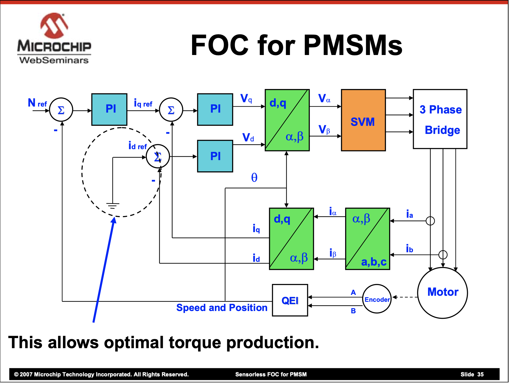
FOC uses current sensors (the number of sensors can vary) on the phases of the motor to get the phase currents ia, ib, and ic. The Clarke transformation converts the three phase currents into two equivalent stator currents, iɑ and iβ. The Park transformation converts the two axis stator currents into two axis rotor currents, iq and id. In order to perform the Park calculation, the rotor angle must be known, so an encoder or a sensorless estimator must determine the angle. The iq current is nominally the torque producing current, while the id current results in a radial force (which happens to be the default state of stepper and gimbal motors). Ideally (but not always) Permanent Magnet Synchronous Motors (PMSMs, which is the umbrella category of BLDC/BLACs) should only produce iq and drive id to zero. Proportional Integral controllers modify the voltages in the q and d directions to achieve these desired currents. These voltages are transformed to the stator frame using the inverse Park transform, then converted to the three phase voltages using a modified inverse Clark transform.
FOC is notably more efficient than block commutation and can significantly reduce motor noise since the motor no longer switches discrete steps. Like block commutation, it works on a very wide range of three phase motors. One downside is the current sensors reduce the efficiency slightly since power is lost in the sensing elements. FOC is also computationally expensive compared to other techniques. Furthermore, the current sensors must be of reasonable quality for FOC to function properly.
Sensored FOC
Sensored FOC uses a position sensor to determine the rotor’s angle. Position sensors can include an optical encoder, a magnetic (hall) encoder, a resolver, and more.
The position sensor allows the motor to perform FOC at any speed, and notably at low speeds. Sensored FOC does not require a position estimator, which reduces the computation complexity compared to its sensorless relative. Unfortunately this sensor must be connected to the motor, must be of decent precision and accuracy, and increases the cost of the system.
Sensorless FOC
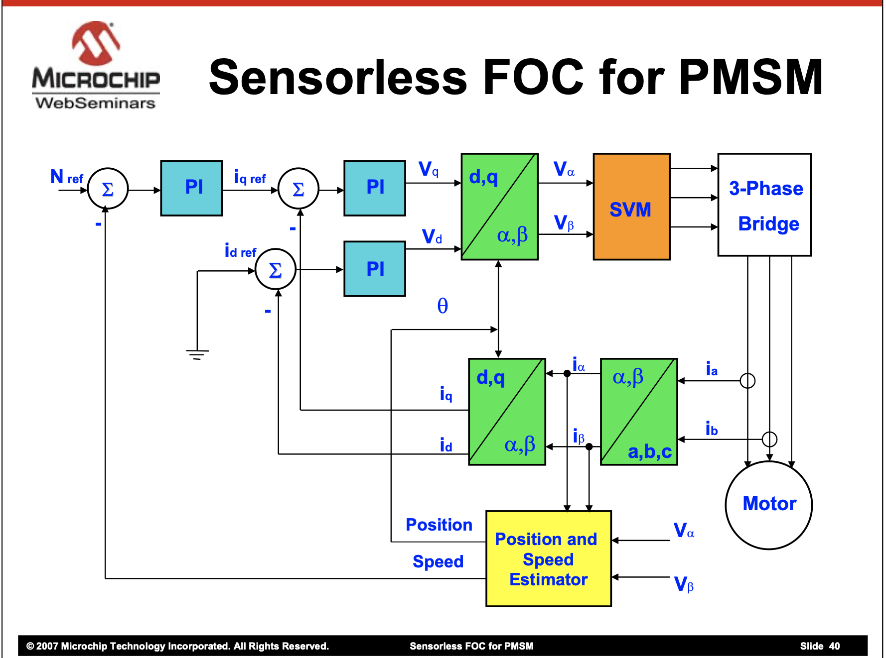
Sensorless FOC uses various computation based estimators to determine the rotor’s electrical position. First, the forward Clarke transformation is performed on the phase currents to determine the current vector in the stator frame. This vector is compared to the applied voltages in the stator frame and a detailed motor model is used to estimate the vector of the bEMF.
The sensorless method has the benefit of being able to connect a controller to virtually any three phase motor and allow it to spin. Unfortunately, many parameters of the motor must be known for the position estimation. Furthermore, this method is computationally expensive, which prohibits very high speed or requires an advanced microcontroller.
Field Estimated Control (FEC)
Field Estimated Control is a new style of vector control that does not require any invasive sensors like current sensors, yet allows all three phases to be active at all times. Instead, an encoder is used for position information and motor voltages and currents are calculated from this information. Like sensorless FOC, a model of the motor is required for these calculations. Like all vector control techniques (FOC falls in this category) any waveform can be generated to accurately match any bEMF shape.
FEC is similar in structure to an inverted sensorless FOC. In sensorless FOC the motor currents are measured and a computed estimate of position is used in the FOC calculation. In the figures this segment is depicted in yellow. In FEC the motor position is measured and the motor currents are computed. This bypasses the forward Clark and Park computations as well as the PI controllers on iq and id. Thus, the computation for this algorithm is reduced by roughly half, allowing for simpler/cheaper microcontrollers or faster computation and switch times. Furthermore, by removing PI controllers on iq and id, FEC has a smaller delay and no current overshoot.
One downside of FEC is its dependence on the encoder. An encoder of medium accuracy, precision, and resolution is required for this technique, and encoders add to the cost of the motor. Another downside of FEC, like sensorless FOC, is it requires good estimates of the motor parameters. Furthermore, FEC is more susceptible to encoder error than FOC due to its high dependence on the encoder. Typically this would happen if the encoder is damaged during use. On the other hand, FEC is less susceptible to motor error, such as parameter changes or damage when compared to FOC. For example, FEC can still operate when one phase of the motor is disconnected or damaged.
Vertiq Advantage
Vertiq uses FEC, we are committed to making FEC meet or exceed all FOC performance numbers. Vertiq makes motor modules (combined motors and controllers) rather than separate motors and controllers. This allows us to implement the appropriate encoders and ensure the proper settings are used incontrol calculations. Vertiq has judiciously chosen encoder configurations that maximize performance and minimize cost. Furthermore, we perform encoder linearization, which is the process of compensating for non-linearities (errors) in the encoder’s output, on every motor. During calibration, the motor learns the unique characteristics of its encoder to ensure the highest accuracy possible. Typical linearization improves the encoder’s accuracy to within 1/8192 of a revolution (0.044 degrees).
An encoder is required for a number of applications and features. Closed loop position control requires position information to close the loop. Low speed/no speed control needs an encoder due to the very small bEMF present at low speeds. Anticogging, the process of electronically compensating for the motor’s cogging torque also requires a position encoder to know what amount of compensation torque is required at any given time and location. Advanced control techniques such as once-per-revolution torque pulsing also requires absolute position information, similar to anticogging, to know when and where to apply extra torque or less torque.


